Smart pot: a small-scale controlled environment for plants#
Due: Jun 7, 11:59 PM
Project#
Learning Goals
The overall objective of this project is to develop a smart pot as a small-scale controlled environment system for a plant to detect various environmental factors and make decisions to achieve the desired environment for the plant to grow. The IoT system includes multiple sensors and actuators that will interact with the plant. The sensing part comprises temperature and relative humidity, PAR, and soil moisture sensors. The actuators are a servo motor, an irrigation pump, an LED, and a lamp. The learning goal is to learn and practice:
- Creating scripts and functions in Blockly
- How to read data from multiple sensors
- How to make decisions based on sensors’ data and user-defined values (set points)
- How to activate and control multiple actuators
Software and Hardware
- BlocklyProp Solo
- Activity Board and Parallax USB programming cable
- PAR sensor
- Temperature/RH sensor
- Soil moisture sensor
- Servo motor
- Pump (peristaltic pump)
- Outlet Power Relay Module
Project Description
This project provides the opportunity to integrate several assignments we have been working on during the quarter. To control and achieve the desired growth environment for plants, we need to develop a program that prompts users to enter the desired values (set points or thresholds) for each parameter we will control. Additionally, it should constantly read the sensor data. Then, it should activate the actuators based on the input data from the users and sensors (Figure 1).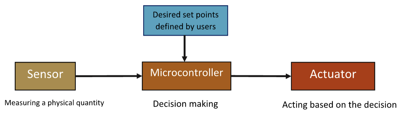
Programming
The code includes a main block and eight function blocks as follows:#
Main block
Define a variable called “iteration” and set it to 1.
Get set points from users and save them as variables
Temperature set point (threshold) saved as “temp_threshold”
Relative humidity set point saved as “rh_threshold”
PAR set point saved as “par_threshold”
Soil moisture set point saved as “moisture_threshold”
A forever repeat block
Print the iteration variable to show how many measurements we have done so far.
Call functions
temp_sensor function to read the temperature value
rh_sensor function to read the RH value
par_sensor function to read the intensity of ambient light
moisture_sensor function to read the soil moisture
led_light function to turn on LED 26 based on temperature
servo_motor function to rotate servo motor based on RH
light_source function to turn the light source ON and OFF based on PAR
irrigation_pump function to turn the pump ON and OFF based on soil moisture
Pause 3000 ms
Increment iteration variable
Clear the terminal
Save your code on your computer periodically.
Submit your code saved as
project_firstName_lastName.svgfile (e.g,project_ali_moghimi.svg)
Table 1 shows what actions we should take based on the inputs from the users and sensors, and Table 2 presents the pin number associated with each sensor and actuator.
Condition |
Action |
|---|---|
Condition |
Action |
—————————————————- |
————————————————————————————————- |
Temperature > threshold defined by users |
Turn on the LED connected to pin 26, assuming we are turning a fan ON. Otherwise, turn off the LED light. |
Relative humidity > threshold defined by users |
Rotate the servo motor 90 degrees, assuming the motor is opening a window in a greenhouse. Otherwise, set the angle to 0 degrees (closing the gate). |
Soil moisture < threshold defined by users |
Turn on the pump until the soil moisture returns to the desired level. The pump is connected to “relay 1”. Otherwise, turn off the pump. |
PAR < threshold defined by users |
Turn on the pump until the soil moisture returns to the desired level. The pump is connected to “relay 1”. Otherwise, turn off the pump. |
Table 1. Taking appropriate actions based on the inputs from users and sensors.
Table 2. Pin number associated with each sensor and actuator.
Sensor/actuator |
Pin |
|---|---|
Temp/RH sensor |
Pin 14 |
Soil moisture sensor connected to the general socket |
Pin AD2 (analog to digital 2) |
PAR sensor |
Pin AD3 (analog to digital 3) |
Servo motor |
Pin 16 and 17, as we did for lab 7 |
The pump is plugged into the relay module that is connected to the “relay 1” socket |
Pin 13 |
The light source is plugged into the relay module that is connected to “relay 2” socket |
Pin 12 |
What to submit:
Submit your code saved as a *.svg file.
A photo of your system.
A short video of your system while working (OPTIONAL).
The project is worth 20% of the total course grade.
We will test your code together in our lab session on June 5th. If we find a bug, you will have two days to debug and submit it again by June 9th with up to a 20% point deduction.
You need to return all the equipment you borrowed by June 10.